Injection mold tooling is the foundation of a successful plastic injection molding project.
A mold does much more than create the shape of a plastic part. In fact, it also affects dimensional consistency, surface quality, assembly fit, cycle stability and the overall reliability of production.
Therefore, a tooling project should not begin with machining alone.
Instead, the process should start with the final plastic part, its material, geometry, expected production requirements and assembly conditions. From there, the mold can be designed and manufactured around the actual needs of the component.
At PALUM, injection mold tooling is connected with DFM, mold engineering, machining, mold trials and injection molding. As a result, tooling decisions can be reviewed together with the behavior of the final molded part.
What Is Injection Mold Tooling?
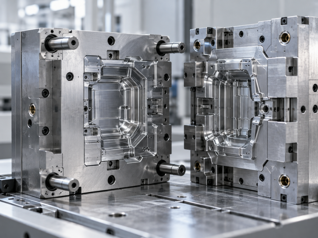
Injection mold tooling refers to the design and manufacturing of the mold used to produce plastic components by injection molding.
Typically, the mold includes several important systems, such as:
- Cavity and core
- Mold base
- Gate system
- Runner system
- Cooling system
- Ejection system
- Slides or lifters when required
- Inserts and other functional tooling components
However, the exact mold structure depends on the project.
For example, a simple housing may require a relatively straightforward mold structure. In contrast, a component with undercuts, side features or complex assembly details may require slides, lifters, inserts or other tooling solutions.
Therefore, injection mold tooling should always be developed around the actual plastic part.
Injection Mold Tooling Starts with DFM
Before mold manufacturing begins, the plastic part should first be reviewed for manufacturability.
This is commonly referred to as DFM, or Design for Manufacturability.
During DFM review, the manufacturer can examine areas that may affect tooling or molding.
These may include:
- Wall thickness
- Draft angles
- Ribs
- Bosses
- Undercuts
- Parting lines
- Gate location
- Ejection
- Assembly interfaces
- Surface requirements
- Areas with potential sink or deformation risk
First, this review helps identify obvious design issues.
Moreover, it allows the tooling engineer to consider how the part will actually fill, cool and release from the mold.
As a result, design adjustments can often be made before steel machining begins.
That is important because changes are usually easier and less costly before mold manufacturing than after the first mold trial.
Part Geometry Influences Mold Design
After the part design has been reviewed, the next step is determining how the mold should be structured.
Part geometry directly affects tooling decisions.
For instance, a part with a straight pull direction may be relatively simple to eject.
However, if the design contains side holes, hooks, clips or other undercut features, the mold may require additional mechanisms.
These can include:
- Slides
- Lifters
- Inserts
- Collapsible features
- Project-specific mold mechanisms
Similarly, deep ribs and bosses can influence filling and ejection.
Therefore, the mold should not be designed as an isolated tool. Instead, its structure should reflect the geometry and function of the finished part.
Material Selection Also Affects Tooling
Injection mold tooling is closely connected to material selection.
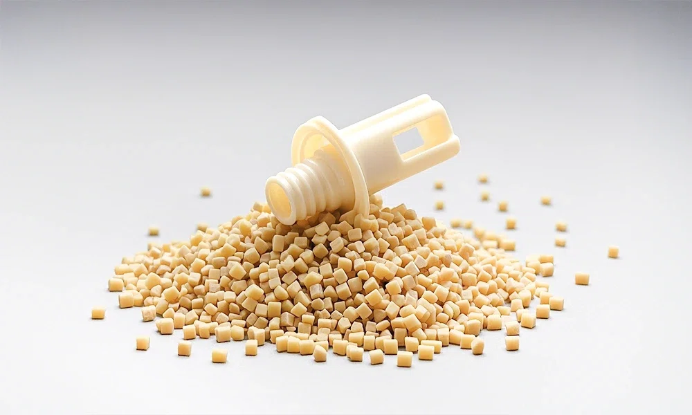
Different resins can behave differently during molding. Consequently, material choice may influence:
- Shrinkage
- Flow behavior
- Cooling
- Warpage
- Gate design
- Mold temperature
- Surface requirements
- Dimensional behavior
Common injection molding materials may include:
- ABS
- PP
- PC/ABS
- PA
- PBT
- POM
- PC
- PMMA
However, the resin family alone is not enough.
For example, different grades of the same material may have different flow or shrinkage behavior.
Therefore, whenever possible, the intended material grade should be confirmed before final mold design.
If the material is not yet finalized, then the manufacturer should at least understand the expected application and material requirements before tooling assumptions are confirmed.
Gate Design Is an Important Tooling Decision
The gate is the point where molten plastic enters the mold cavity.
Although it may look like a small detail, gate design can have a significant influence on the molded part.
It can affect:
- Filling behavior
- Weld lines
- Flow marks
- Surface appearance
- Packing
- Shrinkage
- Part deformation
- Gate vestige
Therefore, gate location should be evaluated together with part geometry and appearance requirements.
For a cosmetic housing, for example, placing the gate in a highly visible area may be undesirable.
On the other hand, for a functional internal component, appearance may be less important than stable filling.
Thus, the best gate design depends on the priorities of the specific project.
Cooling Design Affects Production Stability
Once the cavity is filled, the plastic must cool before the part can be ejected.
Therefore, mold cooling is a critical part of injection mold tooling.
Uneven cooling can contribute to:
- Warpage
- Dimensional variation
- Longer cycle times
- Surface inconsistency
- Uneven shrinkage
In addition, thicker areas of a molded component may cool more slowly than thinner areas.
As a result, cooling design should be considered together with wall thickness, geometry and material behavior.
A well-planned cooling system can help improve process stability during repeat production.
Ejection Should Be Considered Early
After cooling, the molded part must leave the mold without damage.
For this reason, ejection should be considered during mold design rather than added as an afterthought.
Common ejection methods may involve:
- Ejector pins
- Sleeves
- Plates
- Project-specific mechanisms
The correct solution depends on the component.
For example, visible surfaces may require careful ejector placement to reduce noticeable marks.
Meanwhile, deep features or tight geometry may require additional consideration to ensure reliable release.
Draft angle is also closely related to ejection.
Without enough draft, the plastic part may grip the mold surface too tightly. Consequently, ejection force may increase and surface damage can become more likely.
Moldflow and Warpage Analysis Can Support Complex Projects
For selected complex projects, simulation can provide useful information before mold manufacturing is completed.
PALUM can support moldflow and warpage analysis depending on project requirements.
Moldflow analysis may help engineers review areas such as:
- Filling behavior
- Flow balance
- Potential weld line locations
- Pressure distribution
- Gate planning
Likewise, warpage analysis may help identify areas where geometry, material behavior or cooling could contribute to part deformation.
However, simulation should not be treated as a replacement for real mold trials.
Instead, it is a tool that supports engineering decisions before the mold is tested under actual molding conditions.
Mold Manufacturing Turns the Design into a Production Tool
Once the mold design is confirmed, tooling moves into manufacturing.
Depending on the mold, production may involve processes such as:
- CNC machining
- EDM
- Wire cutting
- Grinding
- Drilling
- Fitting
- Polishing
- Texture preparation
- Mold assembly
At this stage, precision matters because every mold component needs to work together.
However, successful mold manufacturing is not only about machining accuracy.
Equally important is whether the final mold can operate correctly during real injection molding.
Therefore, mold assembly, fitting and preparation should always be carried out with the later trial stage in mind.
The First Mold Trial Is a Critical Step
After the mold has been assembled, the next major stage is the mold trial.
This is where tooling moves from engineering assumptions to actual molded parts.
During the first trial, the manufacturer can evaluate:
- Mold filling
- Part formation
- Gate performance
- Ejection
- Surface appearance
- Critical dimensions
- Assembly fit
- Deformation
- Process behavior
In other words, the mold trial shows whether the tooling works as intended.
However, it is normal for a first trial to reveal areas that still need improvement.
Therefore, the goal of a mold trial is not simply to produce the first plastic part.
Instead, it is to collect information that can guide the next tooling or process adjustment.
Mold Adjustment Is Part of Tooling Development
After trial parts are reviewed, the mold may require modification.
For example, adjustments can be related to:
- Part dimensions
- Steel conditions
- Gate design
- Ejection
- Surface areas
- Mold fit
- Cooling
- Functional features
At this stage, the trial result should be compared with the project requirements.
Then, tooling changes can be made based on actual molded-part performance.
Consequently, mold development usually involves an iterative process:
Design → Manufacturing → Trial → Inspection → Adjustment → Retrial
This cycle continues until the mold and molded part reach the agreed project requirements.
Why In-House Mold Trials Matter
A mold manufacturer that can also carry out injection molding has an important advantage during tooling development.
The reason is simple: tooling and molding can be evaluated together.
At PALUM, molds can be trialed in-house using injection molding machines ranging from 50T to 1000T.
Therefore, different mold sizes and plastic components can be evaluated under actual molding conditions.
Moreover, when an issue is found during the trial, tooling engineers and molding personnel can review the result within the same workflow.
As a result, communication between mold manufacturing and injection molding becomes more direct.
From Mold Trial to Stable Production
A mold that produces an acceptable first sample is not automatically ready for repeat production.
The next objective is production stability.
Therefore, manufacturers should review whether the mold can repeatedly produce parts that meet the required specifications.
This may involve checking:
- Repeatability
- Filling stability
- Part dimensions
- Surface condition
- Ejection
- Assembly relationships
- Process conditions
In addition, molding parameters may need to be adjusted during this stage.
Once the process becomes more stable, the project can move toward regular production.
Thus, mold tooling development is not complete until the mold works together with a stable injection molding process.
Single-Cavity and Multi-Cavity Tooling
Cavity quantity is another important tooling decision.
A single-cavity mold produces one part per molding cycle.
In contrast, a multi-cavity mold can produce several parts at the same time.
Multi-cavity tooling can increase output. However, it also introduces additional engineering considerations.
For example, engineers may need to consider:
- Balanced filling
- Runner design
- Cavity consistency
- Cooling balance
- Ejection consistency
- Mold size
- Production volume
Therefore, more cavities do not automatically mean a better mold.
Instead, cavity quantity should be determined according to part geometry, expected volume, tooling requirements and production strategy.
Hot Runner vs Cold Runner Tooling
Another common tooling decision is whether to use a hot runner or cold runner system.
A cold runner mold uses runners that cool together with the molded parts.
A hot runner system, meanwhile, keeps the plastic inside the runner system molten.
Each approach has advantages depending on the project.
Cold Runner
Cold runner tooling may offer:
- Simpler mold structure
- Lower tooling complexity
- Easier maintenance in some applications
However, runner material is normally produced during each cycle.
Hot Runner
Hot runner tooling may help:
- Reduce runner waste
- Support certain large or multi-cavity molds
- Improve specific production layouts
However, it also adds tooling complexity and requires careful system planning.
Therefore, the decision should be based on production requirements rather than treating one system as universally better.
Mold Tooling Should Match Expected Production Needs
Tooling decisions should also consider how the mold will be used later.
For example, a project intended for lower production volume may have different tooling priorities from a project intended for continuous repeat production.
Therefore, the manufacturer should understand:
- Expected quantity
- Part geometry
- Material
- Mold size
- Cavity requirements
- Production conditions
- Maintenance expectations
- Project-specific requirements
This information helps determine an appropriate tooling approach.
Furthermore, it helps prevent overengineering or underengineering the mold.
Tooling Quality Is More Than Surface Appearance
A mold may look clean and well-finished but still produce unstable parts.
Therefore, buyers should evaluate tooling based on actual manufacturing performance.
Important questions include:
- Does the part fill consistently?
- Are critical dimensions stable?
- Does the part eject reliably?
- Is surface quality acceptable?
- Does the mold support repeat production?
- Can the tool be adjusted and maintained effectively?
In addition, the mold should be reviewed together with the resulting molded component.
Ultimately, tooling quality is demonstrated by production performance, not only by the appearance of the steel.
What Should Buyers Provide Before Tooling Begins?
The more relevant information the mold manufacturer receives early, the easier it is to review the project accurately.
Ideally, buyers should provide:
3D Part Files
These help engineers understand the complete geometry.
2D Drawings
Drawings can identify critical dimensions, tolerances and other project requirements.
Material Information
If the resin grade is confirmed, it should be provided before final tooling decisions.
Expected Production Quantity
This can influence cavity planning and mold structure.
Surface Requirements
Textures, cosmetic areas and visible surfaces should be identified early.
Assembly Information
Mating components or assembly requirements can help engineers review functional interfaces.
However, not every detail needs to be finalized before the first discussion.
If some information is still being confirmed, buyers can send the available drawings and project requirements first.
Common Injection Mold Tooling Mistakes
Several problems can be reduced when tooling is reviewed carefully before manufacturing.
Common risks include:
- Starting mold machining before DFM review
- Ignoring material shrinkage
- Using uneven wall thickness
- Designing ribs or bosses without moldability review
- Placing gates without considering appearance
- Underestimating cooling requirements
- Adding insufficient draft
- Ignoring assembly interfaces
- Treating mold trial as a final approval step instead of an engineering stage
Therefore, the best time to solve tooling problems is usually before the mold is finished.
The earlier an issue is identified, the more options the project team normally has.
A Better Injection Mold Tooling Workflow
A practical injection mold tooling workflow can be summarized as:
- Review the drawing and project requirements.
- Confirm material and production information.
- Carry out DFM review.
- Develop the mold design.
- Review moldflow or warpage where appropriate.
- Manufacture and assemble the mold.
- Conduct the first mold trial.
- Inspect the molded parts.
- Adjust tooling and process conditions.
- Retrial where necessary.
- Confirm production stability.
- Move into repeat injection molding.
This sequence may vary by project.
Nevertheless, the key principle remains the same:
Tooling decisions should be verified through the molded part.
From Tooling to Injection Molding Production
Injection mold tooling is not simply the process of machining steel.
Instead, it connects engineering, mold design, manufacturing, mold trials and injection molding into one project workflow.
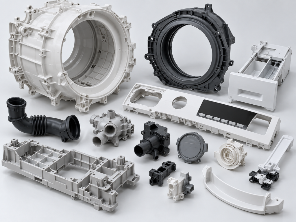
A successful mold should not only match the drawing. More importantly, it should consistently produce plastic parts that meet the actual project requirements.
Therefore, PALUM approaches tooling from the perspective of the final molded component.
By connecting DFM, precision mold manufacturing, mold trials and injection molding, tooling decisions can be reviewed and adjusted around real production results.
If you already have a part drawing, 3D model or existing sample, you can begin by sharing the available project information for an initial tooling review.
Frequently Asked Questions
What is injection mold tooling?
Injection mold tooling is the process of designing and manufacturing the mold used to produce plastic parts through injection molding.
How long does injection mold tooling take?
Tooling time depends on part geometry, mold structure, size, cavity quantity, material and project requirements. Therefore, lead time should be evaluated for the specific project.
Why is DFM important before mold manufacturing?
DFM helps identify design and moldability issues before steel machining begins. As a result, potential tooling changes can often be addressed earlier.
What happens during a mold trial?
During a mold trial, the manufacturer evaluates filling, part formation, dimensions, appearance, ejection and other project-specific requirements using actual molded parts.
Can the same supplier manufacture the mold and produce the plastic parts?
Yes. In addition, coordinating mold manufacturing and injection molding can make it easier to review tooling adjustments together with real molded-part performance.
On This Page
<strong>PALUM Insights</strong>
Practical engineering information for injection molding and tooling projects.